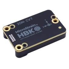
Getting Started
The 3DM-CV7 is
Overview
(Each step is explained in more detail below.)
- Install desired software
- Install the 3DM-CV7
- Capture the gyro bias
- Select the aiding measurements
- Configure the output data stream
- Initialize the Estimation Filter
- Monitor the Estimation Filter status
Install Desired software
There are multiple software offerings for interfacing with the 3DM-CV7, tailored to various applications and levels of experience with inertial products. These offerings are organized below by increasingly lower levels of device control.
SensorConnect™is not required to use the 3DM-CV7. However, it provides an intuitive GUI that greatly simplifies the initial configuration and evaluation process. The remaining steps in this section can be easily performed in SensorConnect™. See Software for more details about SensorConnect™.
ROS drivers provide a standardized framework to easily interface with the 3DM-CV7 . ROS is recommended for applications where ease of integration is prioritized above optimum time synchronization. Examples include waypoint navigation, obstacle avoidance, sensor fusion for SLAM applications, simple embedded startup, etc. See Software for more details about ROS.
MIP SDK is a C and C++ SDK for interfacing with MicroStrain Inertial products at a low level and is the recommend software product for embedded, resource constrained, and time-critical applications. See Software for more details about MIP SDK.
Install the 3DM-CV7
Prior to installation, it is important that users read the instructions on Powering the 3DM-CV7. In addition, it is critical to correctly configure the mounting transform . Installation describes this process in more detail.
Capture the Gyro Bias
Capturing and removing gyro bias is one of the simplest ways to increase sensor performance. Gyro bias can shift during shipping and installation and should be captured and stored in non-volatile memory after sensor mounting, while the vehicle is stationary (including all motors and moving parts.) Additionally, it may need to be captured and stored periodically throughout the lifetime of the application. Once captured and stored it is automatically applied to the gyro data. See the Capture Gyro Bias (0x0C,0x39) command for details. To ensure this command is persistent through power cycling i.e. stored in non-volatile memory (NVM), use the Device Settings (0x0C,0x30) command to save to NVM.
Instructions for how to perform a gyro bias capture using SensorConnect™ can be found here.
Select the Aiding Measurements
The 3DM-CV7's Estimation Filter can accept a variety of aiding measurements to improve its solution.
Example internal aiding measurements include magnetometer.
Example external aiding measurements include true heading .
See Filter Aiding Measurements for more details.
Configure the Output Data Stream
Configure the 3DM-CV7 to output the data quantities required for your application. See Data for a complete list of supported data quantities. This is easily completed through SensorConnect in the "Sampling" tile.
Initialize the Estimation Filter
To run in
Monitor the Estimation Filter Status
The status of the Estimation Filter can be monitored through the Status (0x82,0x10) data channel. For a full description of this message and the Estimation Filter modes, see Filter Status. Health checks can be performed by monitoring and comparing the Filter Uncertainty Messages with the application specific thresholds. For example, attitude can be monitored with Euler Angles Uncertainty (0x82,0x0A).